
 General Usage Guidelines
- Provide accurate human interface.
- Provide guidelines for preliminary work-station or product user, and maintainer anthropometric layouts.
- Provide trade-off, evaluation data, and presentations to the human factors specialist, industrial designer, design engineer, and management.
- Provide accurate dimensional criteria for electro-mechanical “packaging” of components, and to locate controls & displays.
- Provide optimal seating base positions, and define specific adjustment requirements for controls access to the range of 5th Female through 95th Male.
Advantages of using Ergo-link™ 3-D Human Factors Engineering CAD Mannequins:
Key features of employing this cross-over human interface process at concept inception include:
- Increases the probability of designing a successful, quality engineered product at a reduced development cost.
- When utilized at the inception of a project, Ergo-link™ 3-D Human Factors Engineering CAD Mannequins provide effective design guidance in conjunction with functional electro-mechanical design.
- Ergo-link™ 3-D Human Factors Engineering CAD Mannequin models used in layouts will significantly reduce the reiterative time expenditure and related cost.
- Consolidating and stabilizing essential human spatial & interface requirements at the start-up phase will provide subsequent clearly defined design objectives.
- Critical aspects to designing an optimum product or work-station are the combination of delineating functional requirements and utilizing human engineering analytical tools including task analysis, sequential analysis, and anthropometrics.
- The probability of achieving optimum work-station design is significantly enhanced when state-of-the-art computer modeling and accurate human data and is used.
- Ergo-link™ 3-D Human Factors Engineering CAD Mannequin models have enabled SGD, its associate design partners, and its clients to achieve project completions with significant confidence.
- The application of statistically accurate human models to the computer design process ensures not only a functional external interface, but also provides the assembler, installer, and maintainer appropriate accessibility.
- Ergo-link™ 3-D Human Factors Engineering CAD Mannequins are designed to be utilized in any design layout that requires a human interface.
 Applicable utilization:
- Anthropometric layouts for operating vehicles and aircraft work/stations.
- Human Interface solutions for operator controls & displays including GUI and ID.
- Ground & airborne vehicle driver, weapon-station, communication, crew compartment work-station layouts
- Industrial, commercial, and construction vehicle operator cabs/work-station HF layouts for trucks, buses, industrial, and farm vehicle cabs, cranes and excavators.
- Medical, Industrial, consumer, & Commercial product human factors based electro-mechanical layouts, GUI, and ID.
- Complex product component packaging & ID.
- Rapid-prototyping & mock-up fabrication for products and vehicles.
- Production design oversight from concept through production release
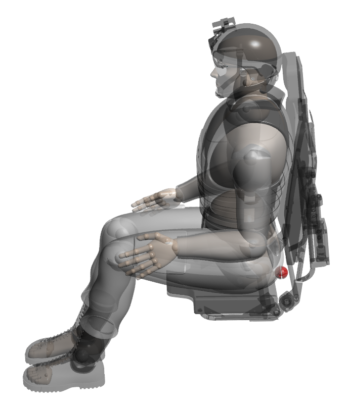
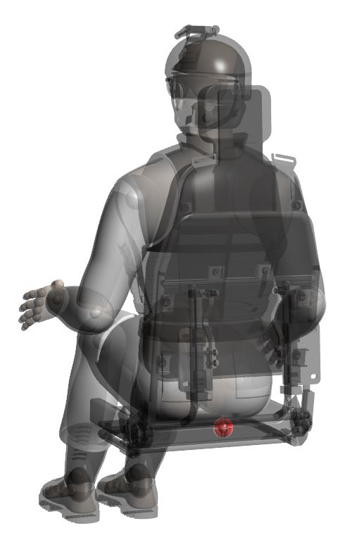
Mannequin Articulation:
Ergo-link™ 3-D Human Factors Engineering CAD Mannequins articulate in all directions at each joint to specific user preference. Limbs can be mated to rotate in parallel with other selected body parts or to major planes to achieve intended positioning. NOTE: Range of movement for limbs and body parts is not preset. The user can apply standard limited range of motion mating. The limbs are mated by a hemispherical ball at each joint intersection, and visible in “Wireframe” mode (can also be viewed in transparent mode).
Body part & equipment/optional features mating is as follows:
- Head – neck
- Neck – torso
- Torso – hip/buttocks
- Hip – thigh
- Thigh – calf
- Calf – ankle/foot
- Upper arm – torso (shoulder joint)
- Upper arm – lower arm (elbow joint)
- Hand palm – fingers (all finger sections articulate)
- SRP (Seat Reference Point) – available for mating to seats
Vision Cone Usage:
- Vision cones are provided for primary and secondary ranges (select transparent mode).
- Cones are monocular or binocular and can be turned “Off” or “On” by selecting the “Hide” or “Suppress “command (can also be viewed in transparent mode).
- To view what the mannequin can see within these zones, simply hide or suppress (or select transparent mode for head/neck) the mannequin head and view the cones from the user position.
- Cones are set at 20 inches (50.8cm) from the eye point, with the maximum recommended viewing distance at 25 inches (63.5cm).
Reach Zones:
- Reach zones include normal & extended reach.
Mating when clothing and equipment is used:
When adjusting or adding mates select the “Wireframe” or transparent mode to provide visual access to spheres at each limb rotation point. The spheres provide simple mating and full range of motion. As is typical in solid modeling, to limit or reset a specific range of motion, select existing component planes to move and hold a limb, body part or equipment in a fixed position, select the part, right click the mouse, and select “FIX”. To release from the fixed position, select “FLOAT”.
Using Ergo-link™ 3-D Human Factors Engineering CAD Mannequin models with other assemblies:
When inserting a mannequin into another assembly such as a vehicle position:
- Insert the mannequin into the assembly
- Dissolve the mannequin assembly for ease of limb articulation (in lieu of using the “flexible” selection for the mannequin).
- When the “Dissolve” method is used, components placed into a top level assembly should be located in folders to ensure a manageable Feature Manager Tree.
When inserting another assembly such as a vehicle position into a mannequin assembly:
- Insert the assembly into the mannequin assembly
- Use the mannequin model to locate the other assembly.
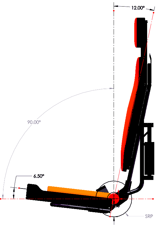
Seat Positioning/General Information:
Seat positioning is achieved by mating the Ergo-link™ 3-D Human Factors Engineering CAD Mannequin models SRP (Seat Reference Point) sphere to the seat SRP. The mannequin SRP is located on the right plane at the intersection of the back and bottom of the buttocks. NOTE 1: The seat SRP point on the seat is dependent on cushion compression which is weight dependent. For example, dependent on seat thickness and density, for a 95th percentile male, the compression is approximately .75 inches (19.05.4mm) dependent on equipment worn at the buttock area of the seat cushion, and .50 inches (12.7mm) compression at the mannequin Scapula (“shoulder blade”) interface with the vertical seat cushion. NOTE 2: Seat base and back angles vary dependent on seat utility. Standard seat base angles for vehicles are generally between 5 degrees and 22 degrees dependent on the type of vehicle (i.e. approximately 5-10 degrees for a bus or truck seat, and approximately 20-22 degrees for a sports car). After setting the seat base angle, the back is positioned to maintain a range of seat to back angle of approximately 90-100 degrees. NOTE 3: Specific type of vehicle military vehicle seating and low profile interiors are often configured to provide “adequate” comfort within available space. Seat pan height and seat cushion depth is determined by available height to accommodate the range of percentiles required.
Static seating (office/home) is purpose based.
- Ergo-link™ 3-D Human Factors Engineering CAD Mannequin models hip and back angles are adjustable, but the SRP sphere is recommended to first be mated as the assembly anchor.
- It is recommended that the hip side plane be mated or “FIXED” to “parallel” (centered) on the seat to allow fore and aft rotation of the torso while locking the hip position.
- The simplest approach is to first mate the mannequin SRP to a separate sphere created on the center SRP of the seat to first “anchor” the mannequin assembly.
- The hand is a separate sub-assembly. To move each digit (finger) separately, either dissolve the sub-assembly or set the hands to “flexible” or create and utilize present finger/thumb positioning.
Configurations Guide:
With the exception of the Ergo-link™ MC (Military Combat) & MT (Military Tanker) mannequins, each 3-D CAD mannequin is designed with one (1) configuration that facilitates ease of use with added configurations that utilize different equipment for including helmets:
- Helmet-mounted NVD’s (Night Vision Devices) with over helmet “stowed” or “in use” configurations).
- Goggles that can be selected to either “stowed” or “in-use” (over helmet or over eye positioning) configurations.
Clothing Patterns/Camouflage:
- Each mannequin model is equipped with a default clothing type. A folder with specific non-standard textures is included with the Ergo-Link™ installation. To modify textures each component in the assembly must be opened and the desired texture selected.
- For military mannequin clothing several camouflage patterns/colors are provided.
Ergonomic Computer Models, Ergonomic Human Computer Models, Ergonomic User-Interface Digital Models, Workstation Design Mannequins, Vehicle Design Mannequins, Vehicle Cab Design Mannequins, User-interface Digital Mannequins